
0 Item(s) in Cart
£0.00
You have no items in your shopping cart.


Details
CFE18 stands for "Can Bus Function Extension" or colloquially also "Can Switch Board" - why is this module needed?
Can bus connections in the vehicle sometimes present our customers with great challenges. Especially in motor sports applications, when electronics have to be accommodated in the steering wheel and information from adjustment knobs (trimpots) or pushbuttons is then to be transmitted via Can Bus.
CANchecked now offers a small add-on module that has 18 connections: 9 for pushbuttons and 9 for analog inputs (0-5V signal). A voltage converter to ensure connection to a 12V vehicle electrical system is also already integrated.
- The CFE18 hardware -
With only 29x27mm, the circuit board is very compact and can be placed anywhere. The pin pitch is 2.54mm - 3.81mm for the power supply for safety reasons.
We have made a hole for attachment, which can be used as a screw connection.
CFE18 - Can Bus Termination
A solder jumper is attached to the circuit board.
If you close this, the Can Bus termination with 120 ohms is active. By default the solder jumper is OPEN .
- Connections -
12V / GND (top) Power supply 6-22V (protected against polarity reversal) A0-A8 9 analog inputs (0-5V) D0-D8 9 digital inputs (maximum 5V) (internal pullup 20-50K) 5V/SGND Power supply for analog sensors or sensor ground CANL/CANH Can Bus connection (Can Low, Can High)
CAN 2.0 A/B – 125, 250, 500, 1000 kbps RX/TX/DTR/GND optional: for possible updates
(additional hardware required)
CAN 2.0 A/B – 125, 250, 500, 1000 kbps RX/TX/DTR/GND optional: for possible updates
(additional hardware required)
- Motorsport steering wheel -
One application would be a motorsport steering wheel. In the picture you can see the approximate size, the steering wheel hub is 50mm in diameter. With only 4 connections via a spiral cable, a wide range of inputs can be transmitted via CAN bus.
Thanks to PT Motorsport Electronics for the excellent example image of how the integration of our Can Switch Board can be done.
- connection options -
Switches (switches) as well as trimpots (adjustment knobs) can be connected to the CFE18.
But sensors such as oil pressure, fuel pressure, boost pressure, exhaust back pressure and integration into a separate housing would also be conceivable.
- CFE18 connector / Default Can Bus Stream -
The input data is queried and transmitted every 50ms (100Hz - variable from 1Hz to approx. 300Hz - depending on the smoothing ). The data is transmitted as "unsigned big endian".
As soon as 12V and ground are connected, the green status LED on the front lights up and the Can Bus data is transmitted.
Can Bus ID: 0x700 ( Base Data CAN ID – changeable)
byte 0 1 2 3 4 5 6 7 BaseID AIN0 0-1023 AIN1 0-1023 AIN2 0-1023 AIN3 0-1023 Base ID +1 AIN4 0-1023 AIN5 0-1023 AIN6 0-1023 AIN7 0-1023 Base ID +2 AIN8 0-1023 bit masked DIN0-7 DIN0 0-1 DIN1 0-1 DIN2 0-1 DIN3 0-1 DIN4 0-1 Base ID +3 DIN5 0-1 DIN6 0-1 DIN7 0-1 DIN8 0-1 unused *version
*from software version 3
- AIN smoothing -
*From software version 3
If the analog inputs fluctuate too much, they can be smoothed out using software. This can be configured separately for each analog input.
The analog inputs are evaluated with each transmission (default. 20Hz).
Attitudesmoothing 0 no smoothing 1 2 2 4 3 8th 4 16 5 32 6 64
For example, if a smoothing factor of 4 is set, the average of the last 16 measurements is taken. As a result, the value becomes calmer (smoother), but also reacts with a delay to fluctuations. Here you have to find a healthy middle ground.
The setting is made via Can Bus - see " Configuration options "
- configuration options -
The following values can be adjusted via Can Bus:
Data CAN ID: with which Can Id the data is sent default: 0x700 Configuration CAN ID: with which CAN Id the board can be configured - RESTART required default: 0x70A Frequency: with which the data is sent via the CAN bus in milliseconds Default: 10ms = 100Hz Can Bus Speed: 1=125kbps, 2=250kbps,3=500kbps,4=1Mbit - RESTART required Default: 3 = 500kbps Mode: 0=default, 1=EMUv3, 2=Haltech IO12B, 3=Haltech IO12A+B, 4=Motec Default: 0 *Smoothing: smoothing of the analog inputs, configurable for each input (0-6) Default: 1
*from software version 3
Byte 0+1 are always 0x0C and 0x0A
Byte 2 feature starting with 0x0A
Features:
can id: 0x0A (high byte) + 0x0B (low byte)
config can id: 0x0C (high byte) + 0x0D (low byte)
frequency: 0x0E
can bus speed: 0x0F
mode: 0x10
can id RX: 0x12 (high byte ) + 0x13 (low byte) from CFE18 v0.8
Example 1: change data can id to 0x600
can id bytes 0 bytes 1 byte 2 byte 3 byte 4 byte 5 byte 6 byte 7 0x70A 0x0C 0x0A 0x0A 0x06 unused 0x70A 0x0C 0x0A 0x0B 0x00 unused
Example 2: change frequency to 50Hz (20ms = 0x14 in hex)
can id bytes 0 bytes 1 byte 2 byte 3 byte 4 byte 5 byte 6 byte 7 0x70A 0x0C 0x0A 0x0E 0x14 unused
Example 3: change can bus speed to 1Mbit
can id bytes 0 bytes 1 byte 2 byte 3 byte 4 byte 5 byte 6 byte 7 0x70A 0x0C 0x0A 0x0F 0x04 unused
Example 4: change mode to EMUv3
can id bytes 0 bytes 1 byte 2 byte 3 byte 4 byte 5 byte 6 byte 7 0x70A 0x0C 0x0A 0x10 0x01 unused
Example 5: change smoothing on AIN1 to 4 (=16)
can id bytes 0 bytes 1 byte 2 byte 3 byte 4 byte 5 byte 6 byte 7 0x70A 0x0C 0x0A 0x14 0x04 unused
(0x14 = AIN1, 0x15 = AIN2, 0x16 = AIN3, 0x17 = AIN4, 0x18 = AIN5, 0x19 = AIN6, 0x1A = AIN7, 0x2B=AIN8)
- Control unit / ECU configuration -
The analog inputs provide a 10-bit resolution and therefore values from 0 to 1023. The value must be converted in the control unit. All values are "unsigned big endian"
Examples:
5V voltage AIN0
0x700 Byte0+1
Multiplier: 5; divisor: 1023; Offset: 0
or multiplier: 0.004887585533
Exhaust gas temperature (type k) AIN7:
0x702 Byte6+7
Multiplier: 1250; divisor: 1023; Offset: 0
or multiplier: 1.2218963832
Either the individual bytes are used for the digital inputs. Eg DIN6: 0x702 byte 6 or the bit mask at 0x702 byte2
eg DIN6: 0x702 Byte2 Mask:0x40
Analog input 4 with a type K converter
Digital input 6
- Documentation / Downloads -
You can also download this page as a PDF here:
More Info
| Manufacturer | CANchecked |
|---|---|
| Fitment | No |
| Colour | N/A |
| Note | No |
- Be the first to review this product
You may also be interested in

CANchecked MFD15 Multi Function Display Nissan Skyline GT-R33 RHD
£198.93 Excl. Tax £238.72 Incl. Tax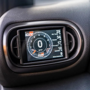

CANchecked MFD32 Multi Function Display Toyota GR Yaris 20+ XP21
£381.21 Excl. Tax £457.45 Incl. Tax
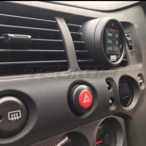
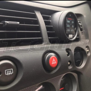
CANchecked MFD28 Multi Function Display Honda Civic EP3 Type R
£343.01 Excl. Tax £411.61 Incl. Tax
© Tegiwa Imports Ltd | Registered in England Number 5798174
Finance provided by PayPal Credit. Terms and conditions apply. Credit subject to status, UK residents only, Tegiwa Imports LTD acts as a broker and offers finance from a restricted range of finance providers. PayPal Credit is a trading name of PayPal UK Ltd, Whittaker House, Whittaker Avenue, Richmond-Upon-Thames, Surrey, United Kingdom, TW9 1EH.

Finance provided by PayPal Credit. Terms and conditions apply. Credit subject to status, UK residents only, Tegiwa Imports LTD acts as a broker and offers finance from a restricted range of finance providers. PayPal Credit is a trading name of PayPal UK Ltd, Whittaker House, Whittaker Avenue, Richmond-Upon-Thames, Surrey, United Kingdom, TW9 1EH.